How To Build A Series Circuit On A Breadboard

Ever looked at a blinking LED and wondered, "How does that little light know when to shine?" Or maybe you've seen a robot wiggle its arms and thought, "Magic!" Well, it's not exactly magic. It's electricity doing its thing. And a super-duper easy way to get started with that electricity wizardry is by building a series circuit on a breadboard.
Think of a breadboard as your playground for electronics. It’s this cool plastic thing with a bunch of holes. No actual bread involved, sadly. But just as satisfying! Today, we’re building a series circuit. Sounds fancy, right? It’s actually the simplest kind of circuit. Like a single-file line of electrical components. Everything is connected one after another. In one continuous loop.
Why a Breadboard?
So, why use a breadboard instead of, you know, trying to solder everything together like a mad scientist? Well, for starters, breadboards are reusable. You can plug and unplug components all day long. No permanent connections. It’s like having a Lego set for electrical circuits! Perfect for beginners. Or anyone who likes to, you know, change their mind a lot. Like me.

Plus, it’s way less intimidating than soldering. No hot irons. No fumes. Just a satisfying click when you push a component in. It’s also surprisingly neat. All those little holes keep things organized. Imagine trying to connect wires without them. It would be a spaghetti monster of epic proportions. And nobody wants that.
What's a Series Circuit, Anyway?
Alright, let's get down to the nitty-gritty. A series circuit is basically a one-way street for electricity. The power, usually from a battery, flows through each component in the circuit, one by one, before returning to the battery. Think of it like a rollercoaster. The power car has to go through every loop and turn before it can get back to the station. If one part of the track is broken, the whole rollercoaster stops. Same with a series circuit.
This "one-way street" aspect is super important. If one component in your series circuit fails, or if a wire gets loose, the entire circuit stops working. Your LED won't light up. Your buzzer won't buzz. It's like that one friend who always forgets their keys and locks everyone out. Annoying, but also kind of a neat characteristic to understand!
The Must-Have Components
To build our simple series circuit, you'll need a few key players. First up, a power source. This is usually a battery pack. Something that provides the juice. Like 3 AA batteries or a 9-volt battery. Gotta have something to get the electrons moving!
Next, we need something to, well, do something. A resistor is a great starting point. Why a resistor? Ah, a fantastic question! If you connect an LED directly to a battery, it's like trying to drink a whole milkshake in one gulp. Too much current, and your LED will pop! Not in a fun, celebratory way. Resistors limit the flow of electricity. They’re like the bouncer at the club, controlling who gets in and how much.
And finally, the star of our show: an LED! Light Emitting Diode. It’s that tiny electronic light bulb that makes blinking things… blink! They come in all sorts of colors. Red, green, blue, even UV if you're feeling adventurous. Just remember, LEDs are a bit particular. They have a positive side (anode) and a negative side (cathode). Get them backward, and they won't light up. They’re like fussy divas of the electronics world.
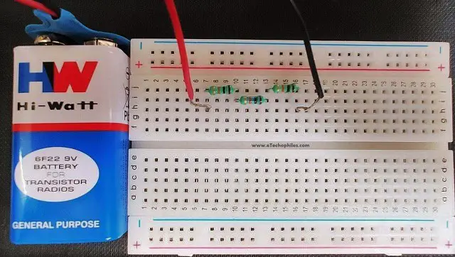
Understanding Your Breadboard
Now, let’s talk about the breadboard itself. See those rows of tiny holes? They’re not just randomly placed. They’re connected internally. Most breadboards have two main sections. The longer rows in the middle? These are for your components. The holes in each of these short rows are all connected together. So, if you plug one leg of a component into a hole, and another component's leg into another hole in the same row, they’re electrically connected. Pretty neat, huh?
Then you have the two long columns on the sides, often marked with red and blue lines. These are called power rails. They run all the way down the board. The red line usually indicates the positive voltage, and the blue line indicates the negative (or ground). These are super handy for distributing power to multiple components without needing a ton of wires.
Let's Build It!
Okay, ready to get your hands dirty? Or, well, your fingers plugged in? Grab your breadboard, battery pack, a resistor (around 220 ohms is a good starting point for most LEDs), and your LED. Make sure your battery pack is off or disconnected for now. Safety first, always!
First, let’s get the power connected. Take your battery pack. It should have two wires, usually red for positive and black for negative. Plug the red wire into one of the holes in the red power rail on your breadboard. Plug the black wire into one of the holes in the blue power rail. Boom! Power distributed.
Now, the resistor. Resistors usually don't have a positive or negative side. They’re like the chill friends in the group. Pick one end of the resistor and plug it into a hole in one of the main rows, away from the power rails. Let's say you plug one leg into row 10, column E.
Next, we need to connect that resistor to the positive power. So, find an empty hole in the same row as your resistor’s first leg (row 10). Plug a jumper wire (those are the colorful little wires with pins on the end) into that hole. Connect the other end of this jumper wire to a hole in the red power rail. Now, your resistor is connected to the positive power!
Now for the LED. Remember, LEDs have a longer leg (anode, positive) and a shorter leg (cathode, negative). The longer leg needs to go towards the positive side of the circuit, and the shorter leg towards the negative. Let’s plug the longer leg (positive) of the LED into a hole in the same row as the other leg of your resistor. So, if your resistor’s second leg is in row 10, column F, plug the LED’s longer leg into row 10, column G.
The shorter leg of the LED now needs to go towards the negative side. Plug it into a hole in the same row but a different column. Let’s say row 10, column H. Now, use another jumper wire to connect the hole containing the LED’s shorter leg (row 10, column H) to a hole in the blue power rail.
And there you have it! You’ve built a series circuit. Time for the grand reveal. Turn on your battery pack.
The Moment of Truth!
If all connections are good, your LED should light up! It might be a bit dim, or super bright, depending on the LED and resistor. But it should glow! That little light is proof that electricity is flowing through your circuit, just as you designed it. How cool is that?! You just made something happen with electricity!
What if it doesn’t light up? Don't panic! This is part of the fun. Double-check your connections. Are all the components firmly in the holes? Is the LED the right way around? Is the battery pack on? Did you use the right resistor for the LED? Sometimes, the simplest things are the most overlooked. It's like trying to find your phone when it's in your hand. Happens to the best of us.
Going Further
This is just the tip of the iceberg, of course. Once you’ve mastered a simple series circuit, you can start adding more components! What happens if you add another LED? Or a small buzzer? You’ll be exploring parallel circuits next, which is like having multiple lanes on your electrical highway. But for now, celebrate your victory! You’ve taken your first step into the amazing world of electronics, one breadboard at a time. Go you!